This article is related to Pelton Wheel Turbine.
A turbine in which a jet of water strikes a wheel tangentially is called a Pelton wheel turbine. Simply put, in a Pelton wheel turbine, water strikes the wheel or impeller tangentially. American designer Lester Allan Pelton invented the Pelton wheeled turbine in the 1870s.
Pelton wheel turbines are best suited for applications with low water flow and high head (pressure). These turbines have large impellers or wheels with multiple blades to absorb the underwater energy. Blades are used in pairs for wheel balancing and efficient operation.
These turbines have atmospheric pressure on the intake and exhaust. The turbine inlet has a movable jet stream. Pelton wheels are used to generate electricity in hydroelectric power plants.
Most liquids and water are practically incompressible and almost all available energy is obtained in the early stages of turbine operation. Therefore, Pelton wheel turbines have only one turbine stage, unlike gas turbines that operate on a compressive fluid (eg gas). Therefore, it extracts all the energy of the water in the initial stage.
Table of Contents
How it Works
The principle of operation of the Pelton turbine is simple.
In hydropower plants, water is mainly stored at higher altitudes. Water stored at high pressure has the highest potential energy.
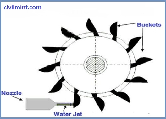
During the operation of the Pelton turbine, high head water enters the turbine nozzle through a pressure pipeline (pressure pipeline). When the water reaches the nozzle, the nozzle converts the potential energy of the water into kinetic energy and enhances the kinetic energy of the water. The nozzle then sends water to the impeller in the form of a jet. ( Refer to the below figure.)
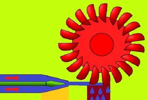
The flow of the water jet hits the impeller or the direction of the impeller. Water jets hit the blades as the nozzle induces a powerful jet of water on the impeller blades. The impeller starts rotating at an excessive speed, and a pin located on the nozzle is used to regulate the amount of water falling on the blade.
When jet water hits the blades of a Pelton water turbine, the water presses on the blades and reduces their kinetic energy. Thanks to the spherical design of the impeller blades, the water jet changes direction and “spins” into the outlet pipe.
In this process, the momentum of the water is transferred to the Pelton wheel turbine. This “impulse” works on the turbine. To achieve maximum efficiency and productivity, this turbine system is designed in such a way that the speed of the water jet is twice the speed of the impeller blades.
Finally, the generator is connected to the impeller shaft and converts the mechanical energy (rotational energy) of the impeller into electrical energy.
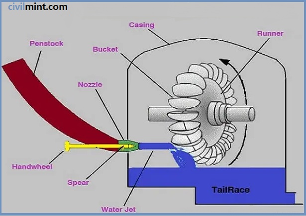
Parts of the Pelton Wheel
- Spear
- Casing or Housing
- Runner or Impeller
- Impeller Blades
- Nozzle
- Breaking jet
For better visual understanding I have shown all the key parts of Pelton wheel turbine in the below image.
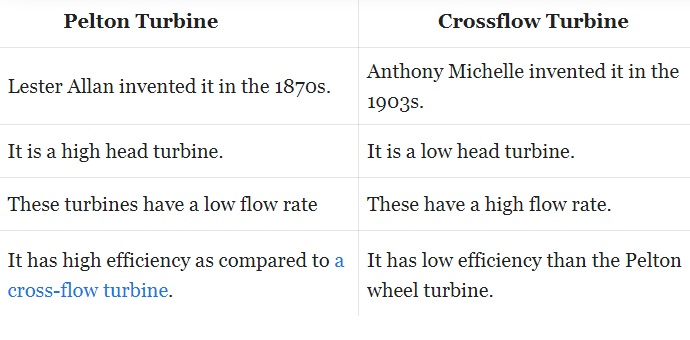
Difference between Pelton Wheel Turbine and Crossflow Turbine
Refer to this table to understand the differences between Pelton Wheel Turbine and Crossflow.